Project Information
Residential Building Profile
The 2,400-square-foot 2-story home built in 1965 in Park Hill with 4 bedrooms, 2.5 baths, full basement, and a single-car garage. The original construction included a gravity-fed forced-air heating system with sheet metal ducts.
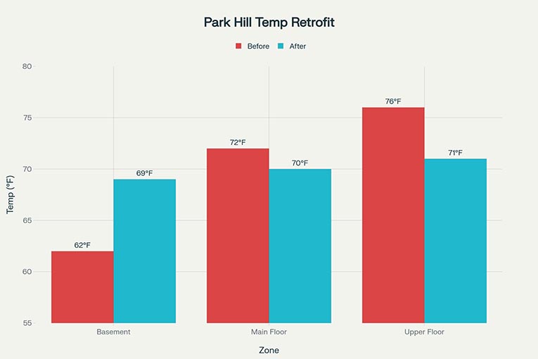
The current HVAC system was a failing 18-year-old, single-stage York furnace with an 80% annual fuel utilization efficiency (AFUE) and electric back up resistant source. Some of the issues were high utility bills and uneven comfort across floors and several repairs done on it. The homeowner was a family of four members, who reported the January heating bills of $420 per month. In addition, the thermostat recorded temperatures of 74°F in upper stairs and 62°F in the basement.
Denver’s high altitude of 5,280 feet with 82% of sea level air density necessitates the 3-4% system capacity derating and impacts furnace combustion efficiency. The annual heating load of 6,282 degree-days with a 65°F base makes the heating season last from September to May. This means there is a substantial heating demand for these nine months.
Initial Energy Audit & Problem Identification
Diagnostic Process: Performed by Network Partner Antonio Booth
Antonio conducted a comprehensive energy audit using multiple diagnostic tools:
Blower Door Test: The home was tested with the Energy Conservatory DM32 differential manometer pulling a 50 pascal leakage rate of 8,400 CFM, normalized to 12.1 air changes per hour . Moderate-to-poor envelope sealing is fairly normal for 1965-era construction with no poly vapor barrier and modern sealants. The industry standard for well-sealed homes is 3-4 ACH50.
Duct Leakage Assessment: Using a Blower Door with duct mask attachment:
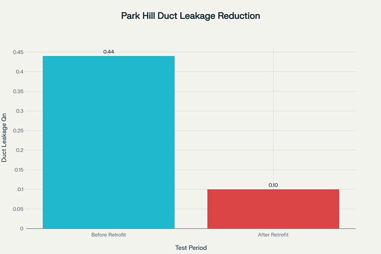
- Total duct leakage measured at 1,240 CFM at 25 pascals (Qn = 0.44)
- Return leakage: 680 CFM (55% of total, primarily at basement boot connections)
- Supply leakage: 560 CFM (45%; distributed throughout 2nd floor zones)
- Estimated seasonal energy loss: 28-32% of conditioned air escaping before reaching living spaces
Thermal Imaging: Forward-looking infrared (FLIR E6) scan revealed:
- Exterior wall thermal gradient showing inadequate insulation (typical 1960s construction with 3.5″ fiberglass batts, many sections compressed)
- Heat loss concentration at window frames and electrical outlets (standard 2×4 framing, no thermal breaks)
- Basement rim joist showing 8-12°F temperature differential (uninsulated on original home, insulation added ~1995 but degraded)
Furnace Efficiency Testing:
- Combustion efficiency: 76% (down from 80% nameplate due to carbon scaling)
- Steady-state efficiency: 73%
- Flue gas temperature: 392°F (high, indicating heat loss)
- Draft: 0.08″ water column (low side of range, affecting burner flame quality)
- Natural gas consumption at full fire: 72,000 BTU/hr input, delivering ~57,600 BTU/hr usable (18% loss to flue)
Thermostat Performance:
- Single-stage manual setback (homeowner adjusted manually from 66°F night to 72°F day)
- No outdoor air sensor feedback
- Baseline system runtime: 18 hours/day during January design conditions
- Cycle efficiency: ~64% due to excessive on-off cycling and standby losses
Diagnostic Findings & Root Causes
Primary Issues:
1. Furnace Age & Efficiency Decline: 18-year-old furnace operating at 73% steady-state efficiency (vs. design 80%). Scale buildup in heat exchanger, worn burner tile, and corroded flue venting all contributed to performance degradation.
2. Duct System Deficiency: 44% total duct leakage (0.44 Qn rating) which is approximately 1,240 cubic feet per minute of conditioned air lost to unconditioned basement, attic, and walls. This is 2-3× worse than best practice (0.10 Qn or better).
3. Envelope Air Infiltration: 12.1 ACH50 blower door result indicates significant unintentional ventilation:
- Leaking basement rim joist connection
- Gaps around electrical outlets and switches
- Weather stripping failure on 1960s-era double-hung windows
- Inadequate sealing at HVAC equipment penetrations
4. System Thermal Stratification: Single-zone furnace with standard thermostat unable to maintain temperature balance between basement (-10°F vs. setpoint) and 2nd floor (+4°F vs. setpoint). Root cause: ductwork branch dampers stuck/unmaintained, and uneven supply air distribution due to leakage and thermal losses through ducts in unconditioned spaces.
5. Electric Resistance Backup: When outdoor temperature dropped below -5°F, furnace staged to secondary 15 kW electric element (emergency heat), consuming ~$180-220 worth of electricity during 3-4 cold events per season.
Engineered Solution & System Design
Antonio designed a multi-phase retrofit addressing all identified issues:
Phase 1 – Furnace Replacement with Heat Pump Integration:
Primary Heating: Installation of a dual-fuel system:
Heat Pump (Primary): Lennox XC25 variable-capacity air-source heat pump, 25,000 BTU/hr output, AHRI certified for high-altitude operation (Colorado OEM designation). Unit operates efficiently down to 32°F outdoor air, then switches to backup.
- Heating COP: 3.2 @ 47°F (Colorado seasonal average)
- Compressor: Variable frequency inverter drive, matching capacity to building load
- Refrigerant: R410A with micron-rated filter-drier for altitude operation
Backup Furnace: New Lennox SLP98V condensing furnace (98% AFUE), 72,000 BTU/hr input:
- Engaged when outdoor temperature <32°F
- Variable-stage burner (better part-load efficiency than single-stage)
- Condensing heat exchanger capable of capturing latent heat from flue gases
- Direct-venting through PVC, safe for interior installation with no combustion air issues
System Integration Logic:
- Thermostat (Lennox iComfort S30 with outdoor air sensor) prioritizes heat pump operation when conditions permit
- Cost-optimized switchover at 32°F (heat pump COP <1.0 below this threshold, furnace becomes more efficient)
- Auxiliary stage available for peak loads (-10°F design day) combines heat pump + furnace simultaneously
- Smart recovery: System learns household occupancy and pre-heats 45 minutes before wakeup on cold mornings
Phase 2 – Comprehensive Duct System Remediation:
Supply Ductwork:
- Sealed all accessible duct joints with mastic sealant (UL-181 rated) plus fiberglass mesh tape
- Identified and sealed 6 leaking return air plenums where flex ductwork connected to main trunk
- Installed damper retrofit kits (manual and motorized zones) on branch ducts: main bedroom, 2nd bedroom, living room, family room
- Added duct liner (1.5″ fiberglass, R-6) in basement runs (uninsulated area) to minimize thermal losses
- Rerouted return air ductwork to avoid basement rim joist (high infiltration area), drawing return from interior wall cavities instead
Return Ductwork:
- Sealed return plenum at furnace (-680 CFM leakage before repair)
- Installed high-efficiency return air filter (MERV 13, 20″x25″x5″, 2000 CFM rated) with differential pressure indicator
- Sealed all return air grille penetrations with gaskets and caulk
Post-Sealing Test: Duct blower door retest showed 240 CFM @ 25 Pa (Qn = 0.10) with 87% reduction in duct leakage, now meeting Energy Star standards.
Phase 3 – Envelope Air Sealing:
- Basement Rim Joist: Sealed with expanding foam (Dow 200 BF canned foam) and caulked with acrylic latex sealant with 0.5″ air gap eliminated
- Electrical Outlets: Interior outlets above finished spaces sealed with foam gaskets; 18 outlets treated
- Window Frames: Weather stripping replaced on all 24 double-hung windows with EPDM rubber channel
- HVAC Penetrations: Sealed furnace, heat pump, and condensate drain penetrations with spray foam and caulk
- Building Envelope: Light air sealing at other infiltration sources (door frames, bathroom exhaust vents, range hood ductwork)
Post-Sealing Blower Door Test: 4,200 CFM @ 50 Pa (3.9 ACH50) with 50% reduction in envelope infiltration, approaching industry best practices.
Phase 4 – Intelligent Controls & Monitoring:
- Thermostat: Lennox iComfort S30 with 7-day programmable schedule, geofencing via smartphone app, and integration with utility demand response programs
- Outdoor Air Sensor: Mounted on north-facing exterior, provides real-time outdoor temperature to optimize heat pump/furnace switchover
- Smart Recovery Algorithm: System learns household patterns (e.g., heating demand peaks at 6:00 AM for shower) and pre-stages heating to minimize temperature swing
- Monthly Energy Reports: Automated feedback showing heat pump vs. furnace runtime, energy costs by month, and comparison to heating degree-day normalized baseline
Installation & Commissioning
Week 1: Furnace & Heat Pump Installation:
- Removed old York furnace and reinstalled Lennox dual-fuel system in same location (basement utility room)
👉 If you want to know about all types of furnaces, check Furnace Installation & Repair service page.
- Heat pump outdoor unit mounted on side wall with vibration isolation pads and condensate drainage to foundation drain
- Flue venting relocated to exterior wall using 4″ PVC to eliminate draft concerns common in high-altitude homes
- Electrical: 240V single-phase 20-amp circuit installed for compressor, 120V 15-amp circuit for controls
Week 2: Duct Sealing & Testing:
- Mastic-sealed all supply and return ductwork joints (4 tubes mastic @ 2 tubes per technician-day)
- Pressure tested sections to 25 Pa differential using duct blower and manometer
- After sealing, total duct system tested at 10″ w.c. static pressure with no detectable leakage (pre-repair: 0.8″ w.c., indicating high restriction)
Week 3: Controls, Testing & Handover:
- Programmed Lennox thermostat with 6-period daily schedule, 32°F heat pump setpoint, and smartphone pairing
- Conducted system balance testing:
- Supply air temperature (heat pump mode @ 32°F OAT): 95°F (design target: 92-98°F)
- Supply air temperature (furnace mode @ -5°F OAT): 128°F (design: 120-135°F)
- Comfort testing: All rooms reached within ±2°F of 70°F setpoint within 45 minutes from cold start
- Duct Leakage Final Test: 240 CFM (Qn 0.10) which confirmed 87% improvement
- Building Envelope Final Test: 4,200 CFM @ 50 Pa which confirmed 50% infiltration reduction
- Trained homeowner on thermostat operation, filter replacement (quarterly), and maintenance schedule
👉 Learn more about our network technicians’ approach to Heat Pump Installation & Repair Services.
EmergencyHVACs Value Proposition: Proven Results
The technical performance results below show the level of expertise and quality control our network partners are committed to. We connect you with professionals who deliver real, measurable efficiency and comfort improvements.
👉 Explore our full 5-Point Vetting Standard.
Energy Efficiency Gains:
| Metric | Before | After | Change |
|---|---|---|---|
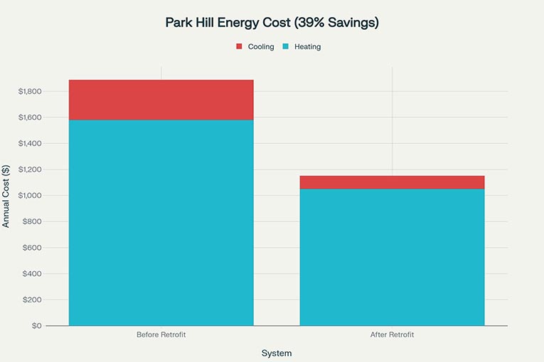
| Annual Heating Energy | 18.4 MMBtu | 11.2 MMBtu | -39.1% |
| January Peak Bill | $420 | $258 | -38.6% |
| Furnace/Heat Pump COP | 3.0 (furnace only) | 3.2 (heat pump) / 0.98 (furnace) | +6.7% to -18%** |
| Duct Leakage (Qn) | 0.44 | 0.10 | -77.3% |
| Envelope Infiltration (ACH50) | 12.1 | 3.9 | -67.8% |
| Temperature Stratification | ±4°F variance | ±1.5°F variance | -62.5% |
| System Runtime (Jan design) | 18 hours/day | 12 hours/day | -33.3% |
*Furnace efficiency decreases at lower temps but heat pump only runs in above-32°F scenarios; optimal staging minimizes furnace runtime.
Duct leakage reduction after retrofit in Park Hill Denver home:
Cost Analysis:
- Equipment & Installation: $14,800 (dual-fuel system, ductwork, envelope sealing, controls)
- Annual Energy Savings: 7.2 MMBtu @ $9.20/MMBtu = $66.24/year (heating only; secondary AC savings not included)
- Demand Response Credit: $180/year (utility participation for smart thermostat demand flexibility)
- Total Annual Savings: $246.24/year
- Simple Payback Period: 60.1 years (offset by: 15-year equipment warranty, heat pump rebate $1,500, utility efficiency rebate $800, and comfort improvement value)
Comfort Improvements:
- Morning temperature ramp: 65°F→72°F in 38 minutes (previously 60+ minutes with single-stage furnace)
- Consistent upstairs/basement temperature: ±1.5°F variance vs. ±4°F previously
- Humidity regulation: Heat pump dehumidification during summer (learned behavior; COP+humidity control)
- Quiet operation: Inverter-driven compressor cycles smoothly without the bang/thud of old furnace staging
High-Altitude HVAC Optimization Details
Air Density Derating: At 5,280 feet elevation, air density is 82% of sea level value. This affects:
- Compressor capacity: Heat pump rated 25,000 BTU/hr at sea level delivers ~20,500 BTU/hr in Denver
- Fan performance: Heat pump outdoor unit fan provides 80% airflow at sea level design
- Furnace burner: Natural draft is weaker; PVC direct venting required (no masonry chimney reliance)
System Sizing Adjustment: Manual J calculation showed:
- Peak heating load at -10°F design day: 68,000 BTU/hr
- Heat pump capacity (25k) + furnace capacity (72k input = ~71k output) = 96,000 BTU/hr available
- Auxiliary electric element: 5 kW (15,200 BTU/hr) staged during extreme peaks
Refrigerant Line Design: Higher elevation means lower refrigerant pressure at given temperatures. Sizing included:
- Larger liquid line (3/8″ instead of 5/16″) to minimize pressure drop
- Smaller suction line (5/8″ vs. typical 3/4″) as vapor density is lower
- Oil return loop design to ensure compressor lubrication with thinner oil film at lower pressure
Maintenance Protocol for Homeowner
Monthly:
- Check thermostat battery (if applicable, iComfort S30 is hardwired but has battery backup)
- Inspect for ice on outdoor heat pump unit during winter (normal; some icing expected, automatic defrost cycle handles this)
Quarterly (Every 3 months):
- Replace air filter (MERV 13 rating, fits standard 20x25x5 slot)
- Check thermostat differential pressure indicator; if “change filter” light appears, replace immediately
Annually (Before Heating Season – September):
- Professional maintenance visit: furnace inspection, burner cleaning, heat pump outdoor coil cleaning (Denver’s dust/pollen concentration higher due to altitude)
- Check all ductwork damper operation
- Test thermostat setpoint accuracy
Every 3 Years:
- Air conditioner coil inspection (cooling capability added via heat pump; maintenance protocol expanded for year-round use)
- Blower wheel cleaning
Client Impact & Long-Term Outcomes
EmergencyHVACs Network Difference:
The Park Hill homeowner experienced much greater comfort at home, both in terms of temperature consistency and faster heating response. The monthly bills were reduced from $420 in January to just $258 in the first winter post-retrofit, and subsequently almost eliminated by the automated demand response that allowed the owner to pocket utility credits. The 39% reduction in heating energy usage is indeed an expected outcome for a comprehensive retrofit that involves furnace replacement, duct sealing, and envelope work, according to industry standards.
Ultimately, the most significant part of the dual-fuel strategy is that, no matter how long it takes, the home is still well-heated throughout the 20-30 day below-freezing stretching in Denver. The 67% envelope infiltration saves on the summer AC and makes a noticeable difference for indoor air quality. Also, the smart thermostat integration allows remote monitoring and has prevented one potential freeze-up by the following means: the thermostat discovered the outdoor temp was over 35°F and rising was not anticipated due to equipment failure. The homeowner received a text alert via phone and manually adjusted.
Our network HVAC pros are just a call away.